Solving a Tough Guarding Challenge
The guard would have to be manufactured from a material that could withstand a catastrophic electric or fire event so that the smoke from the guard would not damage the electrical equipment in the building.
- By Jet LaBarge
- Feb 01, 2016
Editor's note: This case study describes Soo Locks plant operators' four requirements for guards to be placed on four turbine and generator shafts in the plant and how those requirements have been met.
The Challenge
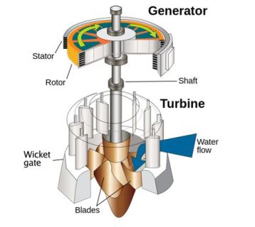
Low head hydraulic power plants have turbines set at or close to the discharge level of the water, with a generator placed above the turbine. (See Figure 1, below.) These two large pieces of equipment are made by different manufacturers and they are connected by an exposed, rotating shaft.
Operators must stand on top of the turbine for inspection and maintenance. Some of the inspection must be done while the unit is operating, placing the operators in close proximity to the shaft. Our company was asked to design guards for four turbine and generator shafts at the Soo Locks in Sault Sainte Marie, Mich.
Background/Requirements
 The turbines are down in moderate-sized pits with little extra room for movement of the operator. Access ports on top of the turbine, close to the shaft, meant that any guarding solution could not be too large or it would interfere with the necessary maintenance of the unit.
The Soo Locks Safety Manager asked the operators of the plant what they wanted in a guard. Their requirements were quite clear:
- They did not want a bulky structure that would make working in the confined area on top of the turbine even more awkward.
- They did not want loose fasteners that could slip free and get lost in the turbine.
- The guard would have to be manufactured from a material that could withstand a catastrophic electric or fire event so that the smoke from the guard would not damage the electrical equipment in the building.
- The guard would have to be easy to install and remove.
Given the list of requirements from the staff, options were limited. A safety lock, preventing users from performing maintenance while the unit was running, was not an option because the generators cannot shut down without scheduled downtime. Completely enclosing the shaft with a fabricated box was discussed. A metal box would be much too unwieldly and heavy for this application. A plastic box would be lighter in weight but still too big for the space requirements given.
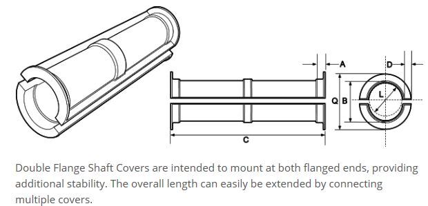
The final option was to custom-tool a fitted shaft cover with ribs for stability and captured hardware for mounting. Although this option was the most expensive, it was the best option given the requirements.
Solution
We received prints from when the units were installed, dated in the mid-1940s. Although the prints gave a good starting point, we still had to construct solid models of the units, double-checking the models against the actual units.
The first requirement was that the guard be close fitting to the shaft, in order to keep as much space in the pit as possible for the operator. By choosing to have a custom-tooled shaft cover, this guard was drawn to the specifications. The main plastic guard sections were pre-assembled using our safety captured fastener system—to ensure that the fasteners would stay with the guards and prevent accidental loss. These fasteners met requirement number two.
This modular guard was made from Kydex T, a thermoformable plastic with a rating of UL Std. 94 V-0, 5V. This met requirement number three, the ability to withstand a fire or electrical catastrophic event. When fully assembled, the guard would be over 18 inches wide and 8 feet tall; by making the guard in identical sections, the cost for tooling stayed low, as only one mold was necessary.
To meet the fourth requirement, each half of the guard, although 8 feet tall, weighed less than 20 pounds. This made the halves easy to transport and easy for one person to install around the shaft.
We worked with the staff at the power plant to devise a way of fastening the guards to the top of the turbines. The power plant operator did not want to drill and tap into the structure of the turbines because, if a problem occurred, it would be extremely expensive to correct. Instead, the guards were fastened to the turbines with weld nuts that could not compromise the structural integrity of the turbines.
The guard had to be stabilized toward the top of the unit, as well as securely fastened on the bottom. We used commercially available extruded aluminum for the braces.
Results
We were able to meet all of the requirements listed by the U.S. Army Corps of Engineers, as well as stay on budget. The customer was so pleased with the shaft guard that it has returned for further projects.
This article originally appeared in the February 2016 issue of Occupational Health & Safety.