Protecting Against Arc Flash with "Safety by Design"
There are additional steps companies can take to mitigate arc flash hazards and remove workers from harm’s way
- By Erhan Cokal
- Oct 01, 2019
An arc flash is defined as a hazardous explosion of energy from an electrical circuit, or a type of discharge that results from a low-impedance connection through air to ground or to another voltage phase in an electrical system.
In the United States, arc flashes occur as often as five to 10 times per day. Many of these incidents result in injuries, and some are even deadly.
Creating a heat blast of up to 35,000 degrees Fahrenheit, arc flash incidents can also damage equipment and interrupt business operations, leading to significant economic losses. The cause can be as simple as a rodent, a misplaced tool, humidity issues, or another element in the breaker area that compromises the electrical “spacing” between energized components. Essentially all electrical systems of voltages 200V or greater are susceptible to arc flash incidents.
To protect electrical systems from these disastrous effects, electrical professionals must comply with OSHA enforced electrical safety standards in their state and local jurisdiction. The National Fire Protection Association’s NFPA 70E1, Standard for Electrical Safety in the Workplace, outlines a six-step process for the proper design and installation of electrical systems: develop and audit electrical safe work practices policy, conduct an arc flash risk assessment to evaluate the likelihood of occurrence and severity of arc flash hazards, follow strategies to mitigate and control arc flash hazards, conduct regularly scheduled safety training and audits for all electrical workers, maintain electrical distribution system components and ensure adequate supply of personal protective equipment (PPE) and proper tools that act as the “last line of defense” for exposed workers.
However, there are additional steps companies can take. Incorporating a “safety by design” approach through the engineering controls helps mitigate arc flash hazards by significantly reducing the arc flash energy levels and removing workers from harm’s way.
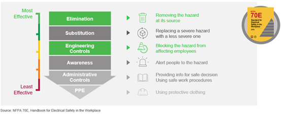
The Figure 1 illustrates the six types of risk control methods arranged in order of effectiveness. At the top of the list is “Elimination”—in other words, disconnecting the circuit from the source, LOTO, and verifying the absence of voltage.
The Engineering Controls option reduces risk without worker involvement (for example, GFCI protection, or barriers). The Elimination, Substitution and Engineering Controls are usually applied at the source and are less likely to be affected by human error. The line side isolation solution has focused engineering controls in conjunction with other methods to lower the overall risk level. The final line of defense is PPE (Personal Protection Equipment). It needs to be properly rated for the hazard, whether it is shock or arc flash or both.

Safety by Design
The amount of arc flash energy reduction will be determined by an engineering analyses, which will always be a function of the upstream circuit breaker or fuse. This is because arcing time is the key determining factor for arc flash energy. Since incident energy is proportional to arcing time, the use of a faster-acting devices is key. As a result, proper selection of overcurrent protective devices and systems—in particular, selecting control devices that will quickly clear arcing faults from the power system—is a powerful mitigation strategy.
There are choices for retrofitting a “safety by design” approach into switchgear, even if the system is decades old. For example, digital relays with overcurrent sensing can now be added to the low-voltage side of a service transformer designed to trip an existing upstream device. Or, light sensors capable of detecting arcs in just a millisecond can be installed within switchgear compartments. A comprehensive look at the system through a safety lens can identify the right options for almost any installation.
Selecting an arc flash mitigation method is a challenging task for many facilities. A simple, reliable and affordable design is expected. In order to achieve this challenging task, here are a few critical questions to ask in the early stage of the system design:
1. How can I reduce the hazard risk?
2. What is my PPE goal?
3. Which operations do I need a PPE, maintenance, troubleshooting?
4. Is service continuity or equipment damage a concern for my system and process?
5. What is my budget to achieve the goal?
6. What is the restriction for additional construction like exhaust plenums?
The answers to these questions will shape the system design.
Consider these recommendations while selecting arc flash mitigation techniques: reduce AFIE (Arc Fault Incident Energy) level, or PPE, as much as possible, improve service continuity, reduce exposure to live parts, simplify commissioning and usage to reduce human risk factor, optimize cost for Capex and Opex and save space with the minimum footprint and less construction.
Arc Flash Assessments
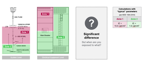
Within electrical equipment, the arc flash risk can vary dramatically, and this typically results in a maximum “zone” of risk associated with the line-side of the main circuit breaker. Another zone of risk, typically an order of magnitude less, exists on the load side of the main circuit breaker. The question is, what is the sufficient isolation in between line side and load side of an electrical enclosure?
A risk assessment should include evaluating the incident energy in each of these zones and creating an understanding of proximity risk, that is, what is the chance that an arc, created downstream of the main circuit breaker, could transfer to the line-side of the main circuit breaker? Serious consequences would result if this were to happen and the worker was wearing PPE appropriate only for the load side risk or vice versa.
The case study below indicates the risk environment.

How do you know if the zones are well separated and distinct? Unfortunately, given today’s practices, there is no present consensus in the industry on how this should be determined. Therefore, whoever performs the arc flash hazard analysis study must rely on “engineering judgment” and is responsible for determining the chance that an arc flash could transfer and when it could not. This can be difficult for a person who is not familiar with arc flash analysis methods or lacks detailed knowledge of electrical equipment construction. At best, this type of uncertainty does not seem well aligned with the potential risk, a situation for which further development in standards and practices is both warranted and likely.
Furthermore, even if the switchboard is put into an electrically safe working condition, the act of testing to verify if equipment is de-energized could expose a worker to electrical hazards, so a complete risk assessment must also include system operational modes including removal from operation and restoration to operation. These also present gaps in the current practice also subject to “engineering judgement.”
One solution to address these gaps is to build a vault to contain the arc that provides the “separate and distinct” isolation of the zones, along with improved arc flash management of Zone 1, the line side of the main circuit breaker. This significantly reduces the level of risk the worker faces throughout the equipment.
Closing the Judgement Gap with Passive Line-Side Arc Isolation
There is a new type of line side arc isolation module that addresses these concerns directly and is likely to be recognized as an incident energy reduction method in the 2021 Edition of NFPA 70E. This new design can potentially be applied in many types of low-voltage distribution equipment, providing positive isolation between protective zones and reducing the chance that employees are inadequately protected based on inaccurate or incomplete arc flash risk assessments.
The system addresses arcing faults in the equipment at the location where incident energy levels are typically the highest, the line side of the main circuit breaker. The main circuit breaker can also be used as a lockout/tagout point for all work within the equipment outside of the main breaker. Features such as embedded thermal sensors and “absence of voltage” detectors can further help in day-to-day operation and maintenance of the breaker as well.
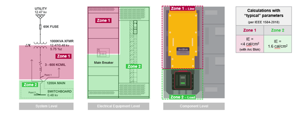
Figure 3. shows the same case study shown in Figure 2. with the line side isolation system. This solution reduces the AFIE on the line side and does not allow any plasma or arc transfer from load to line or line to load side. In other words, it is a system to minimize the human risk factor and reduces the AFIE level.

Conclusion
Electrical hazards pose a significant safety and financial risk for businesses and their employees. OSHA mandates that any work on electrical equipment must be performed in a safe manner that poses no undue risk of injury. To comply with these regulations, businesses must employ the latest protective designs such as line side arc isolation to enhance workplace safety. When businesses use the latest technologies available coupled with internal processes like risk assessment and evaluation, they protect their greatest asset: their people.
References:
1. NFPA 70E 2018
2. Antony Parsons, Jonathan Gray, Living With Arc-Flash Mitigation, May 2019, IEEE Industry Applications Magazines
3. Antony Parsons, Tim Faber, Mark A. Metzdorf Enhancing Worker and Equipment Protection Through Passive Arc-Fault Mitigation
This article originally appeared in the October 2019 issue of Occupational Health & Safety.